
光收发器测试设备:构建 100G–800G 测试平台
The tests an optical transceiver must pass are defined by IEEE 802.3 and by multi-source agreements (MSAs) such as those for QSFP-DD and OSFP modules. As lane rates rise from 25G NRZ to 100G and 200G PAM4, the instrument list grows: PAM4 needs a BERT that can generate and analyze four-level signals, a sampling oscilloscope with TDECQ analysis, and tighter control of optical power and wavelength.
This guide maps each transmitter, receiver and module-management test to the instrument class that performs it, then gives a bench “recipe” for 100G, 400G and 800G. It also covers the difference between R&D and production benches, and what to check when you cut cost with pre-owned instruments. It is vendor-neutral: examples come from Keysight, Anritsu and Yokogawa because they are common in transceiver labs.
A note on terms used below: NRZ (non-return-to-zero) carries one bit per symbol on two levels; PAM4 (four-level pulse amplitude modulation) carries two bits per symbol on four levels. “GBd” (gigabaud) is the symbol rate, so a 53.125 GBd PAM4 lane carries a line rate of 106.25 Gb/s, which delivers a 100G lane after FEC and coding overhead.
What you need to measure (Tx, Rx and module management)
A transceiver bench measures three things: the quality of the transmitted optical signal, the receiver’s ability to recover data at low power, and the module’s electrical and management behavior. The exact parameters and limits come from the IEEE 802.3 clause or MSA for the module type.
Transmitter
- Eye diagram and TDECQ. For PAM4 signals, transmitter and dispersion eye closure quaternary (TDECQ) is the key transmitter quality metric. It is measured on an equivalent-time sampling oscilloscope with a reference receiver and equalizer defined by the standard. NRZ links use eye mask tests and TDP-type metrics instead.
- Extinction ratio (ER). The ratio of the high and low optical power levels.
- Outer optical modulation amplitude (OMA outer). The difference between the outer optical levels of the PAM4 signal, used together with TDECQ.
- Average optical power. Per lane, measured with an optical power meter or the oscilloscope’s optical channel.
- Center wavelength and side-mode suppression ratio (SMSR). Measured with an optical spectrum analyzer (OSA). Wavelength alone can be measured with a wavelength meter.
Receiver
- Receiver sensitivity. The lowest optical power at which the receiver still meets the target bit error ratio (BER). Measured by attenuating the input with a variable optical attenuator (VOA) while a BERT counts errors.
- Stressed receiver sensitivity (SRS). Sensitivity measured with a deliberately impaired signal, with a defined amount of eye closure, to reflect worst-case link conditions.
- Overload. The highest input power the receiver can handle while meeting the BER target.
- BER pre- and post-FEC. Most 100G-per-lane PAM4 links rely on forward error correction (for example RS(544,514) “KP4” FEC). Tests often report pre-FEC BER against a threshold such as 2.4 × 10⁻⁴, and some testers also analyze FEC symbol error distributions.
Module management
- Power consumption against the MSA power class.
- Management interface: I²C access to CMIS (for QSFP-DD and OSFP) or SFF-8636 registers, and digital diagnostic monitoring (DDM) values such as temperature, voltage, bias current and optical power.
- Temperature corners: performance across the module’s operating case temperature range, using a thermal head or chamber.
[DIAGRAM PLACEHOLDER: Tx path (BERT pattern generator → compliance board → module Tx → optical splitter → DCA optical module / OSA / power meter) and Rx path (reference transmitter or module Tx → VOA → power monitor tap → module Rx → compliance board → BERT error detector)]
The core instruments and their roles
A complete bench combines a BERT, a sampling oscilloscope (DCA), optical power meters and attenuators, a spectrum or wavelength instrument, switches for automation, and supporting gear. Each covers a specific set of tests.
BERT / pattern generator
The BERT generates the electrical test pattern (for example PRBS31Q or SSPRQ for PAM4) that drives the module’s transmitter, and its error detector counts errors on the receiver output. For PAM4 it must support the right symbol rate: 26.5625 GBd for 50G lanes, 53.125 GBd for 100G lanes, and higher rates for 200G lanes.
Examples: the Keysight M8040A high-performance BERT for PAM4 and NRZ R&D work, and the Anritsu MP2110A BERTWave, which combines a multichannel BERT and sampling oscilloscope in one instrument. See our 比特误码率测试仪 category.
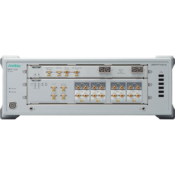
Anritsu MP2110A BERTWave: representative image from the wnot.cn product page (the site labels it as not a photograph of the exact unit).
Sampling oscilloscope (DCA) with optical modules and clock recovery
An equivalent-time sampling oscilloscope (Keysight calls it a DCA, Digital Communications Analyzer) measures the transmitted optical eye, TDECQ, ER and OMA. It needs three parts: a mainframe, an optical sampling module with a reference receiver suitable for the rate, and a clock recovery source (a hardware module or, on some systems, a built-in option).
Examples on wnot.cn:
- Mainframes: Keysight N1000A DCA-X and the older Agilent 86100C DCA-J
- Compact optical sampling oscilloscope: Keysight N1092D DCA-M (multiple optical channels in one unit)
- Plug-in module: Keysight 86116C optical/electrical sampling module
- Clock recovery: Keysight N1077A optical/electrical clock recovery
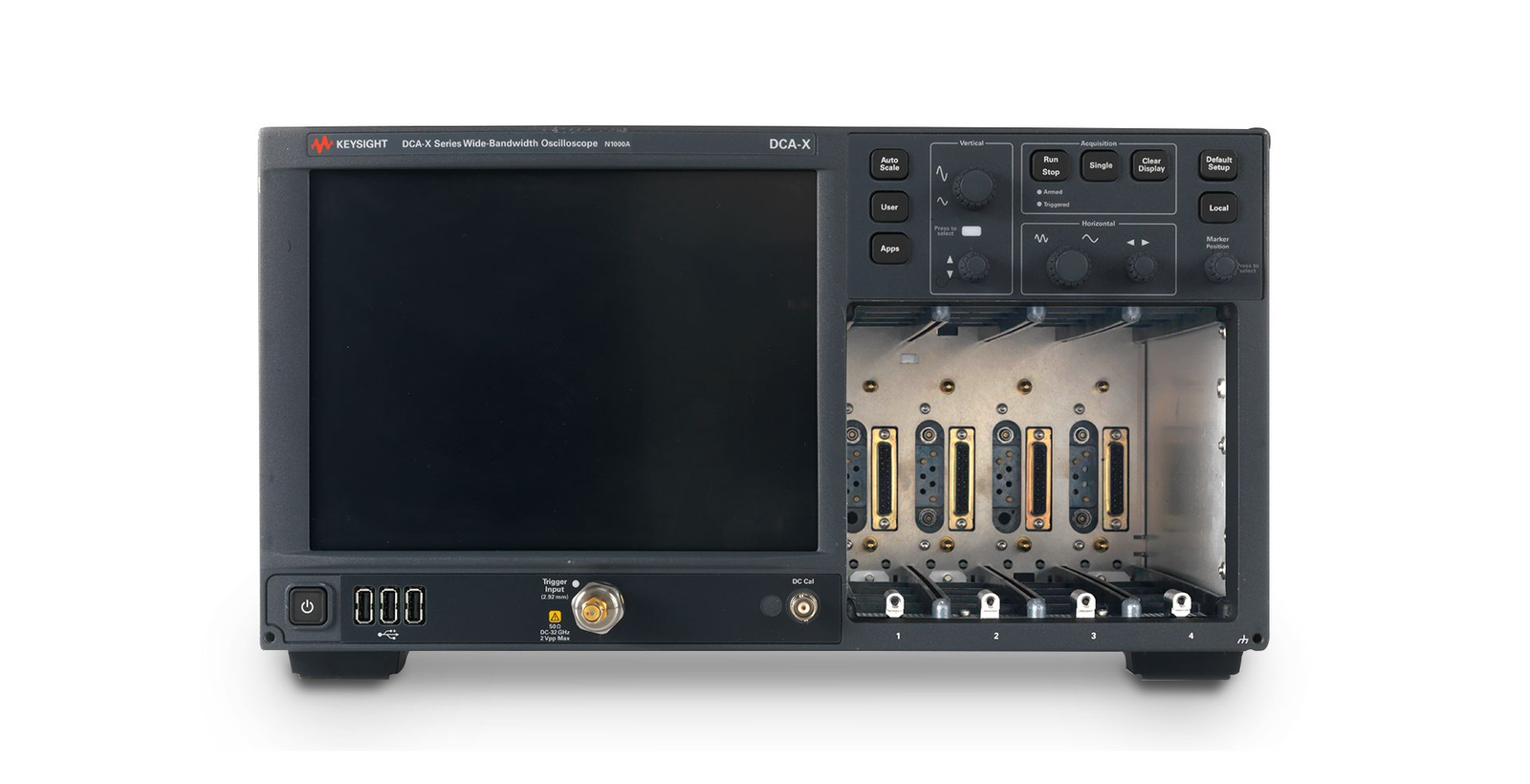
Keysight N1000A DCA-X: representative image from the wnot.cn product page (the site labels it as not a photograph of the exact unit).
TDECQ is calculated in the oscilloscope software (FlexDCA on current Keysight platforms) and requires a PAM4 analysis license. Older mainframes may need a software or firmware update, an external PC or a specific module generation to run TDECQ.
Optical power meter and VOA (sensitivity sweeps)
Optical power meters measure average power, and a VOA sets the optical power arriving at the receiver during sensitivity and overload tests. Many VOAs have a built-in power monitor, which simplifies the setup.
Examples: the Keysight N7745C multiport optical power meter, the Keysight 81634B power sensor module, the Keysight N7764A four-channel VOA, and the Agilent 81576A VOA module. See 光功率计.
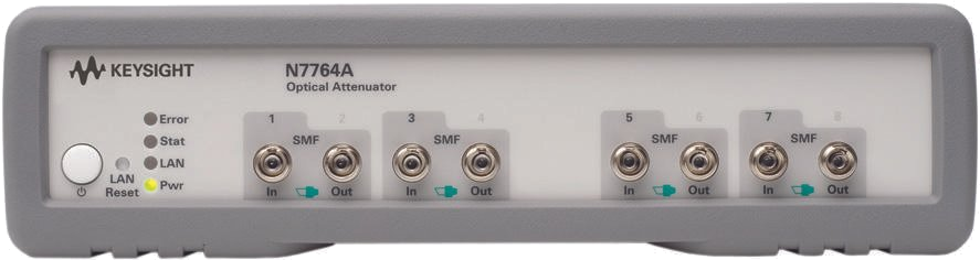
Keysight N7764A: representative image from the wnot.cn product page (the site labels it as not a photograph of the exact unit).
OSA / wavelength meter (wavelength, SMSR, CWDM/LAN-WDM grids)
An OSA measures center wavelength, spectral width and SMSR for each lane, and checks that lanes sit inside the CWDM or LAN-WDM grid that the standard specifies. A wavelength meter measures wavelength with higher accuracy and speed but does not show the full spectrum.
Examples: the Yokogawa AQ6370D OSA (600 to 1700 nm, per its wnot.cn listing) and the Keysight 86122C multiwavelength meter. See 光谱分析仪.
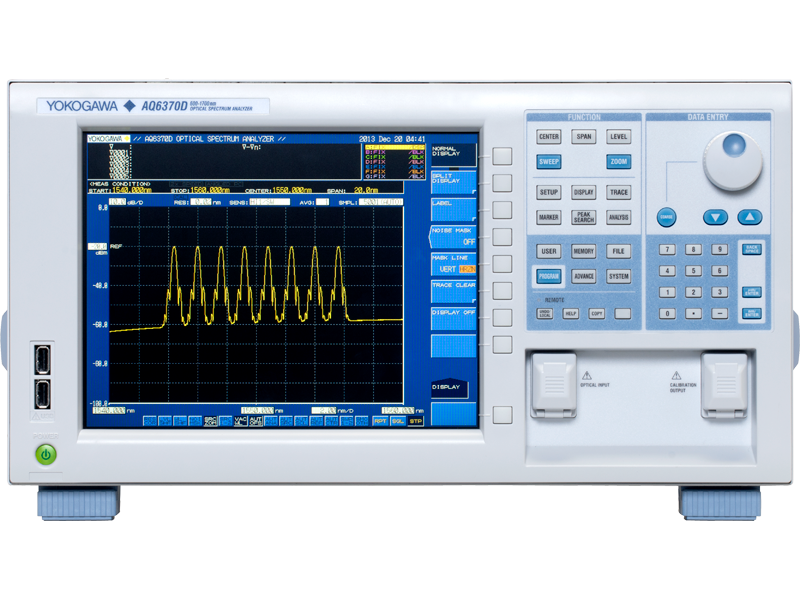
Yokogawa AQ6370D: representative image from the wnot.cn product page (the site labels it as not a photograph of the exact unit).
Optical switches for multi-lane automation
On 400G and 800G modules with four or eight lanes, an optical switch routes each lane to a shared DCA, OSA or power meter in turn, so you do not need one instrument per lane. Example: the Keysight 81595B optical switch module. Account for switch insertion loss and repeatability in your power measurements.
Supporting gear
- Programmable DC power supply to power the module and measure its current draw. See 交流/直流电源.
- Module compliance board (MCB) or host board with a high-speed electrical interface for the form factor (QSFP28, QSFP-DD, OSFP) and an I²C or management interface.
- Thermal control: a thermal head, thermal stream or chamber for temperature corners.
- Fiber, connectors and cleaning tools: patch cords, attenuators and connector inspection scopes. Dirty connectors are a common source of power and BER problems.
Bench recipes by data rate
The table below summarizes a typical bench for each data rate tier. Lane counts and symbol rates follow common IEEE 802.3 and MSA variants.
| Module rate | Typical lane structure | BERT | DCA and modules | OPM / VOA | OSA / wavelength | Notes |
|---|---|---|---|---|---|---|
| 100G | 4 × 25G NRZ (25.78125 GBd), e.g. 100GBASE-LR4 / CWDM4; or 1 × 100G PAM4 (53.125 GBd), e.g. 100G-DR/FR/LR | 4-lane NRZ BERT; or PAM4 BERT at 53.125 GBd | Mainframe with NRZ optical module and clock recovery; PAM4 + TDECQ for single-lambda | 4 VOA channels or 1 VOA with switch; power meter | OSA for LAN-WDM/CWDM grid and SMSR | NRZ benches are the most common used setups |
| 400G | 4 × 100G PAM4 (53.125 GBd), e.g. 400GBASE-DR4 / FR4; or 8 × 50G PAM4 (26.5625 GBd), e.g. 400GBASE-LR8 | 4- or 8-lane PAM4 BERT | DCA with PAM4 TDECQ license, optical module at the right rate, clock recovery | Multichannel VOA (4–8), multiport power meter | OSA for FR4/LR8 grids; wavelength meter optional | Optical switch reduces DCA channel count |
| 800G | 8 × 100G PAM4 (53.125 GBd), e.g. 800G-DR8 / 2×FR4; or 4 × 200G PAM4 | 8-lane PAM4 BERT (or 200G/lane capable) | DCA with PAM4 TDECQ, multi-channel optical sampling or switch | 8-channel VOA and power meter | OSA for 2×FR4 / FR4 grids | 200G/lane needs newer DCA modules and BERTs |
R&D characterization vs production test
R&D and production use different instruments because their goals differ: R&D needs the most accurate, flexible measurement of each parameter, while production needs fast, repeatable pass/fail testing of many modules.
- R&D characterization uses modular, high-performance instruments: a full-featured BERT with jitter and stress options, a DCA with high-bandwidth optical modules and flexible reference receivers, a high-resolution OSA, and separate power meters and VOAs. Engineers vary equalizer settings, temperature and stress conditions to understand margins.
- Production test favors all-in-one testers such as the Anritsu MP2110A BERTWave, which combines BERT and sampling scope functions, plus multi-channel parallel test, optical switches and automated software. Test time per module and repeatability matter more than the last fraction of a dB.
Many companies use one R&D bench to define the test limits, then several simpler production stations that correlate against it.
A useful way to plan purchases is to separate instruments that must be at the leading edge of your data rate (the BERT, the DCA optical module and clock recovery) from instruments where older models remain fully adequate (power meters, VOAs, switches, DC supplies and many OSAs). Spending is usually best concentrated on the first group.
Production benches also depend on things that are easy to overlook when planning purchases:
- Test time. Each step (thermal stabilization, eye acquisition, sensitivity sweep) adds seconds per module. Parallel lanes, optical switches and fast power meters reduce total time.
- Correlation. Production stations should be checked regularly against a golden module and against the R&D bench, so that pass/fail limits mean the same thing on every station.
- Fiber management. Connector cleaning and inspection, and the number of matings per day, affect yield and repeatability more than small differences in instrument specification.
- Software. Most production systems are driven by in-house or third-party automation software. Check that the instruments you buy have drivers or SCPI support for your platform.
Cutting cost with used equipment: what to watch
Pre-owned instruments can reduce the cost of a transceiver bench considerably, especially for DCA mainframes, lightwave mainframes, power meters and VOAs. The main risk is buying an instrument without the options, modules or firmware your test needs.
- Options and licenses. Check that PAM4 analysis, TDECQ, clock recovery rates and BERT pattern or symbol-rate options are installed and tied to the unit’s serial number. Ask for a screenshot of the license list.
- Module and mainframe compatibility. Older DCA mainframes may not support newer modules, or may need a specific firmware or FlexDCA version.
- Optical connector types. Check whether inputs are FC/PC, FC/APC or another interface and whether connector adapters are included. Mating APC and PC connectors damages both.
- Reference receiver calibration. TDECQ and OMA results depend on the calibrated frequency response of the optical sampling module. Ask for its calibration status and date.
- Power sensor calibration. Optical power sensors drift; check the calibration certificate covers the wavelengths you use.
- Lane rate headroom. Equipment that is fully adequate for 100G NRZ may not support 100G-per-lane PAM4. If you plan to move to 400G or 800G within a few years, check whether the mainframe can accept newer modules and software, so that you upgrade modules instead of replacing the whole platform.
- Lightwave mainframes for power and VOA. Older modular lightwave platforms, such as the Keysight 8163/8164/8166 mainframes with power sensor and attenuator modules, can be a low-cost way to add power meter and VOA channels. Our upcoming guide to the Keysight 8163, 8164 and 8166 lightwave mainframes covers what to check.
At TXRX Instrument, every instrument we sell is inspected and functionally verified by our engineers (per our 测试设备销售 page). TXRX pre-owned equipment comes with a 6-month warranty. For pre-owned units, a calibration certificate or test report is available (as stated in your quotation). New equipment carries the manufacturer’s standard warranty as published by each brand and includes a factory calibration certificate. There is no fixed return window: if an inspection confirms a product-quality issue, TXRX will repair or replace the unit. Returns for reasons other than product quality are not accepted.
For related products, browse 光学与通信测试 and 示波器 (including DCA sampling oscilloscopes), or see our Optical Communications & Silicon Photonics solution page.
How to set up a receiver sensitivity test (summary)
- Connect a reference transmitter (or a known-good module transmitter) through a VOA and a power monitor tap to the receiver under test.
- Drive the transmitter with the specified pattern from the BERT pattern generator.
- Connect the receiver’s electrical output on the compliance board to the BERT error detector.
- Set the VOA to a high power, confirm error-free operation, then reduce power in steps.
- At each step, record received optical power and BER.
- Sensitivity is the lowest power at which the BER still meets the target.
For stressed receiver sensitivity, the reference transmitter is replaced by a stressed-eye source calibrated to the conditions in the standard, usually by tuning the stress on the DCA before the test. For overload, increase the VOA power until the BER exceeds the target or the maximum specified input power is reached, taking care not to exceed the receiver’s damage threshold.
FAQ
What equipment is needed to test an 800G optical module?
A typical 800G bench needs a multi-lane PAM4 BERT, a sampling oscilloscope (DCA) with suitable optical modules, clock recovery and TDECQ software, optical power meters, variable optical attenuators, an OSA or wavelength meter, a programmable DC supply and a module compliance board. Optical switches help share instruments across eight lanes.
What is TDECQ and which instrument measures it?
TDECQ (transmitter and dispersion eye closure quaternary) is the IEEE metric for PAM4 transmitter quality. It estimates how much extra signal power the receiver would need because of eye closure. It is measured on an equivalent-time sampling oscilloscope, such as a Keysight DCA, with an optical reference receiver and TDECQ analysis software.
Can one instrument test both BER and the eye?
Yes. All-in-one testers such as the Anritsu MP2110A BERTWave combine a multichannel BERT and a sampling oscilloscope, so one instrument can measure BER, eye parameters and, with the right options, TDECQ. They are popular for production. R&D benches often use separate BERTs and DCAs for flexibility.
Why do I need a variable optical attenuator?
A VOA sets the optical power reaching the receiver. By reducing power in controlled steps while a BERT counts errors, you find the receiver’s sensitivity. By increasing it, you test overload. VOAs with built-in power monitoring make the sweep faster and more repeatable, and multichannel VOAs handle several lanes at once.
Can older DCA mainframes test 400G?
Sometimes. It depends on the mainframe’s support for current optical modules, a clock recovery solution for 53.125 GBd PAM4, and PAM4/TDECQ software. An older mainframe paired with a newer module may work for some tests but not others. Check the module and software compatibility lists before buying.
Do I need an OSA for transceiver testing?
For WDM modules, usually yes. An OSA measures center wavelength, SMSR and spectral width, and confirms lanes are inside the CWDM or LAN-WDM grid. For single-wavelength modules or wavelength-only checks, a wavelength meter can be enough, and it is often faster in production.
Building or expanding a transceiver bench? Send us your data rate, form factor and test list. We’ll propose a matched bench, new or pre-owned, with options verified.